

Tech: remote controlling heating systems
The aim of this article is to share different well-functioning solutions to be able to remotely control heating systems or other devices WITHOUT major modifications or interventions in the control system itself, so that the original function is preserved and that components can be replaced later without too much work.
Today's society is becoming more and more characterized by digitization and IOT (internet of things). After wondering why a refrigerator needs to have internet access, I quickly found out the advantages of having heating systems online controlled. Regardless of whether it concerns a pellet stove, heat pump or other heating system that is older than just a couple of years, I always get the same reply from the manufacturer: "Sorry, we use proprietary systems, your XX (insert desired machine) cannot be connected to a network or be remote controlled."
So the alternative is to built it yourself. Wouldn't it be easy to be able to remotely control these devices without having to physically press a button? Be it in order to automate operation, lower the temperature when you are away, adapt temperatures for tenants, run diagnostics or read out error messages
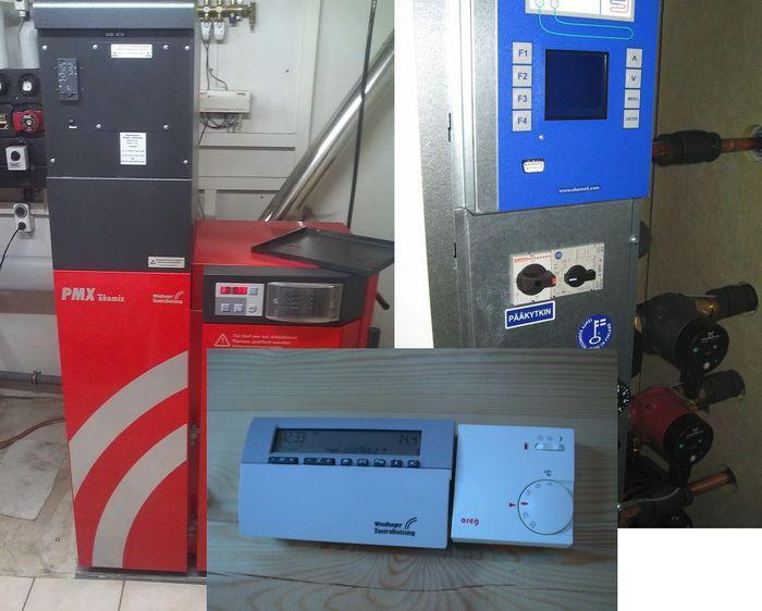
UNIT 1: Heat pump control.
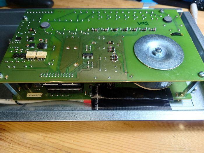
Dismantle the logic / control unit and disconnect all cables. Ensure clean working conditions and avoid static electricity (earthing).
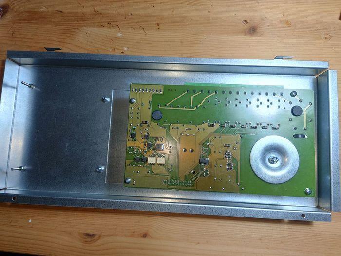
Find the solder points for switches you want to remotely control and measure with an ohmmeter the output position (NO/NC = normally open or normally closed).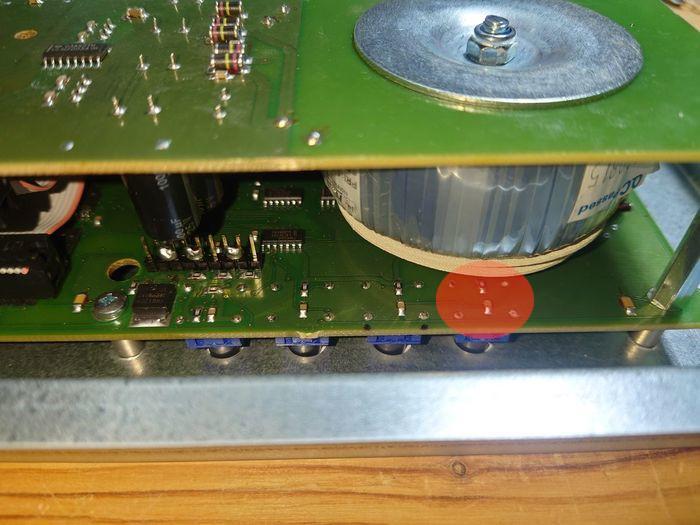
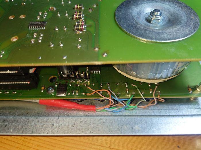
Then solder cables to switches you want to remotely control. In this case I chose to use Cat5 network cable which is practical with the correct cable cross section, color coding and since it is compact enough for 4 switches (8 wires).
It goes without saying that the warranty on the machine you are soldering on will immediately be terminated with such interventions, but we want to improve the result, not create short circuits or fire traps. Read example 3 (further down) for a solution that does not require soldering.
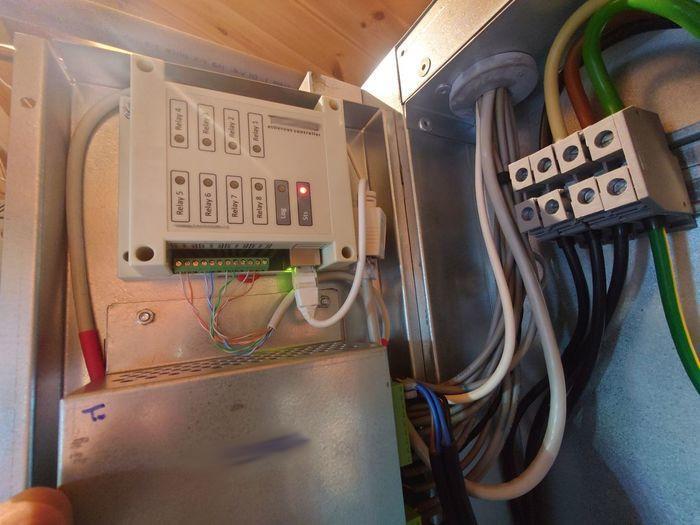
For the actual remote control, we use an Ethernet controller that can pulse / turn on/off relays. These are available from a number of companies, either as individual units like this one here, or as part of a home automation system. The vast majority of machines have enough space to accommodate such a unit, well protected from mechanical and thermal stress as well as water splashes.
We connect the Ethernet controller to the cabling we have created, use each relay as a switch and connect the Ethernet and power. Of course there are WLAN solutions, but here I wanted a stable connection via network cable which has the advantage of being able to supply power to the device at the same time (PoE - Power over Ethernet). When the device does not support PoE like in this case (12VDC), we either use a splitter cable (passive PoE injector as here) or feed in the power directly on conductor pairs 4-5 and 7-8 in line with the passive PoE 802.3af standard.
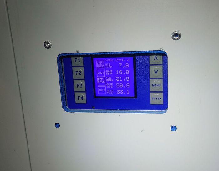
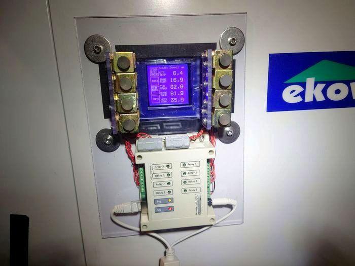
UNIT 2: Room management / control panel.
If you look closely at the circuit board, you will often discover small holes near components such as switches. These "service holes" can be used to solder cables without damaging other microchips, SMD components, etc. Here, too, we fix the cabling with tape and lead it forward neatly.
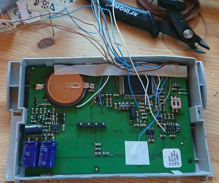
As described in example 1 (above), this control was connected to an ethernet controller. The 8 most important multifunction keys were selected. In this case, the display is read out through a web camera. The keys have been preserved in their original function and work as before.
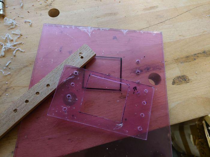
UNIT 3: Example where it is not possible to solder on the circuit board,
e.g. where the control is encapsulated, where one does not want to lose the warranty or due to a lack of knowledge of soldering (circuit board).
This solution requires a little more mechanical work, and I chose to use plexiglass because it is easy and quick to process without special equipment. If you are reading this, you probably have access to a workshop that might even be equipped with a CNC mill or 3d printer. It then provides completely different (more advanced and elegant) possibilities than presented here, but the version shown works well.
The goal is to "press" a button, remotely controlled. We achieve this with the help of electromagnets (push solenoid). These smart inventions use little electricity and can be found in a variety of tools and machines, from cars to old tape recorders. Their function is to open doors and latches, open and close valves, move robot mechanisms, etc.
These can be bought cheaply at an online store / China, but the version shown here is disassembled from old mechanical records from the 80s/90s. The new ones are much lighter and more compactly built. It is important to find out the right strength, usually expressed in N (Newton) or kg.
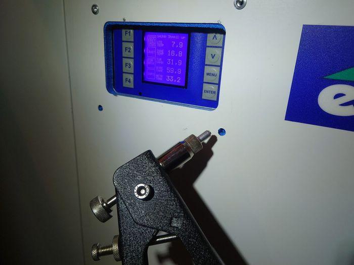
I found a simple method to check the correct force for pressing a button, without utilizing special equipment: Use a kitchen scale with, for example, a ballpoint pen, put both parts up against the switch to be pressed and press until the switch makes contact / activates. At the same time, read the weight in kilograms on the scale of the scale. Most pressure switches will not need more than a couple of kg max. Then choose a solenoid that has a little more strength to overcome the starting current.
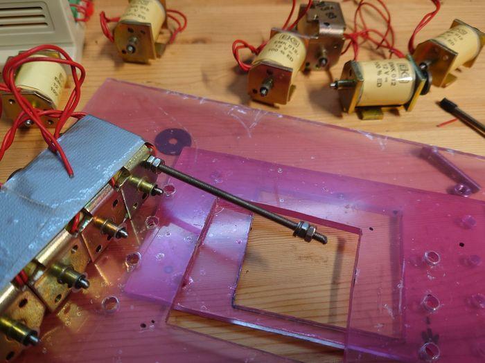
Electromagnets come in a variety of designs. Before, the pull version was most common, but this type is easily modified by extending the rod that goes through the winding. If you buy new, most are now offered as push/pull.
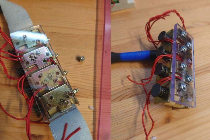
The electromagnets chosen here were too big and did not fit exactly over the switches (I needed 4 in a row). The solution was to make extensions in the form of screws that are spring-loaded and nuts (or washers) that are positioned so that the electromagnets press them down.
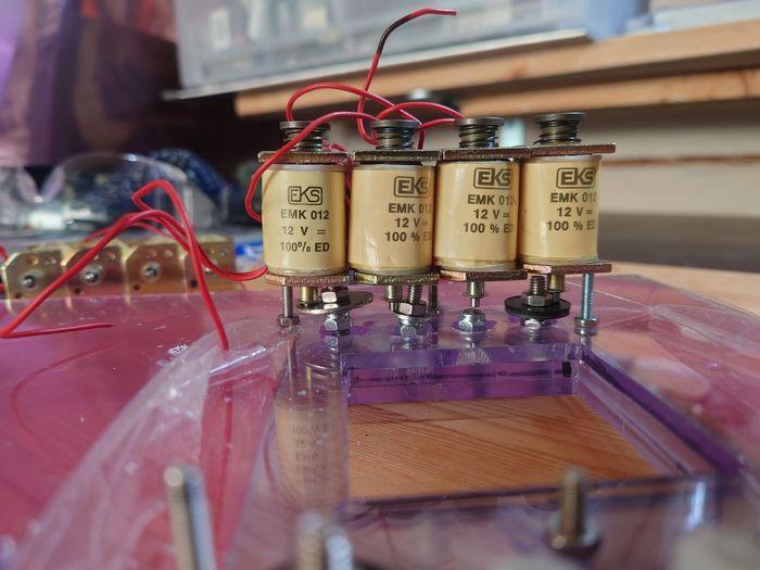
Using machine screws has the advantage of being able to precisely adjust the distance between the electromagnet and the switch. After the pre-assembly and testing, everything is dismantled and fixed with loctite so that vibrations from compressors etc. cannot unscrew the screws.
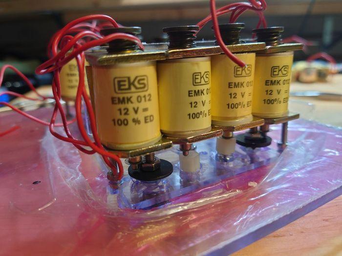
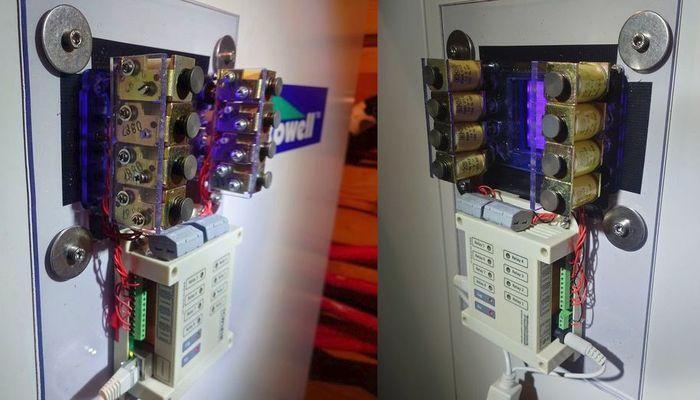
The electromagnets are fully adjusted, screwed onto a handy plexi board together with the Ethernet controller and prepared for installation. The controller is calibrated so that it provides voltage (12VDC in this case) for 1 second at a time. It is equivalent to pressing a button. The spring load then pulls the pin back.
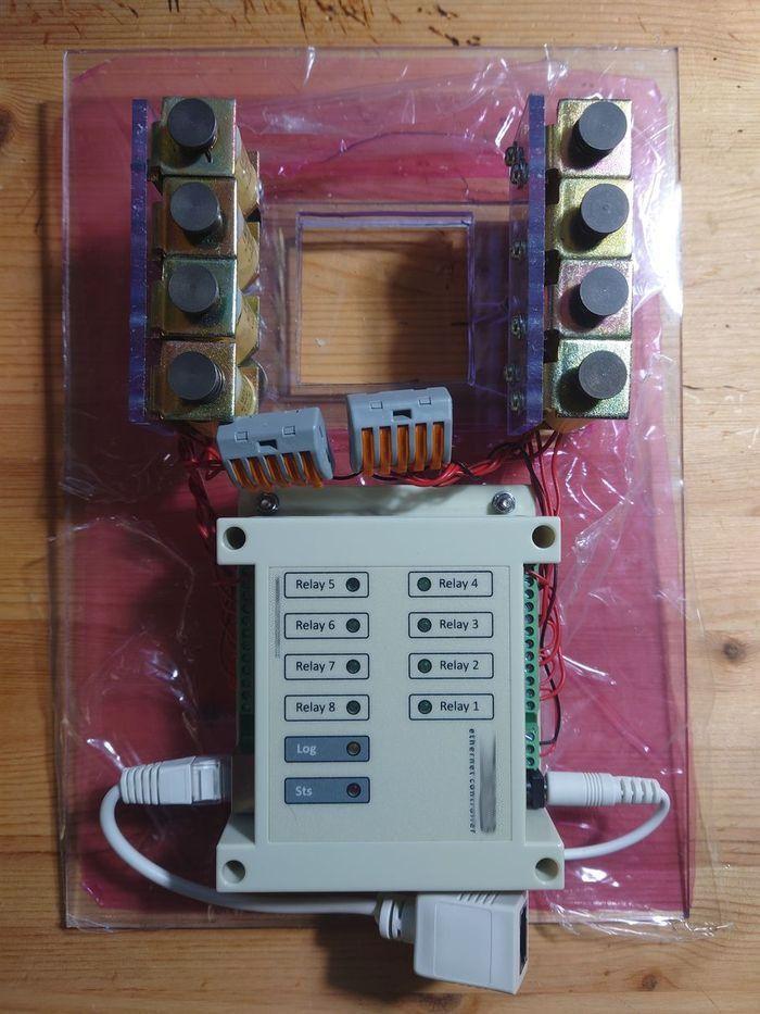
A neat way to attach equipment to surfaces is to use blind nuts. Widely used in aviation for inspection hatches on aircraft, e.g. these only need access from one side for assembly. They ensure stable connections.
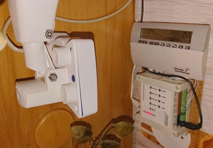
Fully assembled remote control: Control panel can still be pressed manually by pressing on top of the electromagnets. NO modification of the electronics!
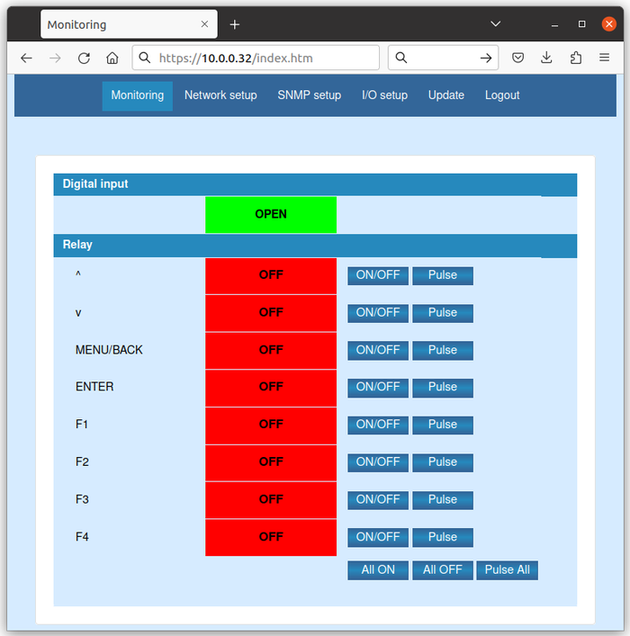
Screenshot from graphical surface of ethernet controller. This is browser-based and thus works on all operating systems without the need to install any software. No programming required. By pressing "pulse" the electromagnet will trigger the specified interval (in my case 1 second) at a time.
The aforementioned how-to can of course be used on all other imaginable systems that use control panels such as awnings, alarm systems, remote controls, garage doors, light and sound systems, pools, you name it.
As always: The article is to be considered a personal opinion with no guarantee of completeness or correctness. I will always make sure to use the best possible sources. The use of the recommendations is the responsibility of the reader. Read the disclaimer here and use common sense. Thanks.
If this description provided inspiration, please get in touch and send some photos, and these will be uploaded here.
Back
All comments are moderated before being published. Your email will not be visible